error: espcomm_upload_mem failed when uploading a sketch
I am new to the whole arduino scene. I have connected my wifi module (esp8266 v01) to my arduino Uno like this:
http://www.teomaragakis.com/hardware/electronics/how-to-connect-an-esp8266-to-an-arduino-uno/
And have downloaded the arduino ide framework so that I may be able to use the arduino IDE as opposed to sending AT commands through the serial monitor.
When trying to upload an example sketch that sends a http request that I found on github, I get the following error:
    Arduino: 1.8.4 (Windows 8.1), Board: "Generic ESP8266 Module, 80 MHz, 40MHz, DIO, 115200, 512K (64K SPIFFS), ck, Disabled, None"


Archiving built core (caching) in: C:UsersYasmeenAppDataLocalTemparduino_cache_354217corecore_esp8266_esp8266_generic_CpuFrequency_80,FlashFreq_40,FlashMode_dio,UploadSpeed_115200,FlashSize_512K64,ResetMethod_ck,Debug_Disabled,DebugLevel_None_____9d1d735445f8d7bf19746e2177d24e71.a

Sketch uses 285417 bytes (65%) of program storage space. Maximum is 434160 bytes.

Global variables use 38688 bytes (47%) of dynamic memory, leaving 43232 bytes for local variables. Maximum is 81920 bytes.

error: failed reading byte

warning: espcomm_send_command: cant receive slip payload data

error: failed reading byte

warning: espcomm_send_command: cant receive slip payload data

error: failed reading byte

warning: espcomm_send_command: cant receive slip payload data

error: failed reading byte

warning: espcomm_send_command: cant receive slip payload data

error: failed reading byte

warning: espcomm_send_command: cant receive slip payload data

error: failed reading byte

warning: espcomm_send_command: cant receive slip payload data

error: failed reading byte

warning: espcomm_send_command: cant receive slip payload data

error: failed reading byte

warning: espcomm_send_command: cant receive slip payload data

error: failed reading byte

warning: espcomm_send_command: cant receive slip payload data

warning: espcomm_sync failed

error: espcomm_open failed

error: espcomm_upload_mem failed

error: espcomm_upload_mem failed
After looking online and researching, I can see that it has something got to do with flashing the firmware or something. I came across this question:
ESP8266 error: espcomm_upload_mem failed while uploading sketch
and the answer did say that he bought a converter.. what does this mean? Does it mean buying this?:
https://www.amazon.co.uk/gp/product/B06Y3FNGJF/ref=oh_aui_detailpage_o00_s00?ie=UTF8&psc=1
I really need help, been stuck on this for the past few days now and seriously contemplating whether to get the arduino wifi shield since it comes prebuilt with wifi.. even though it costs quite a lot!
arduino-uno esp8266 arduino-ide
asked Sep 28 '17 at 12:30
dfqupwndguerrillamaildedfqupwndguerrillamailde
11112
add a comment |
I am new to the whole arduino scene. I have connected my wifi module (esp8266 v01) to my arduino Uno like this:
http://www.teomaragakis.com/hardware/electronics/how-to-connect-an-esp8266-to-an-arduino-uno/
And have downloaded the arduino ide framework so that I may be able to use the arduino IDE as opposed to sending AT commands through the serial monitor.
When trying to upload an example sketch that sends a http request that I found on github, I get the following error:
    Arduino: 1.8.4 (Windows 8.1), Board: "Generic ESP8266 Module, 80 MHz, 40MHz, DIO, 115200, 512K (64K SPIFFS), ck, Disabled, None"


Archiving built core (caching) in: C:UsersYasmeenAppDataLocalTemparduino_cache_354217corecore_esp8266_esp8266_generic_CpuFrequency_80,FlashFreq_40,FlashMode_dio,UploadSpeed_115200,FlashSize_512K64,ResetMethod_ck,Debug_Disabled,DebugLevel_None_____9d1d735445f8d7bf19746e2177d24e71.a

Sketch uses 285417 bytes (65%) of program storage space. Maximum is 434160 bytes.

Global variables use 38688 bytes (47%) of dynamic memory, leaving 43232 bytes for local variables. Maximum is 81920 bytes.

error: failed reading byte

warning: espcomm_send_command: cant receive slip payload data

error: failed reading byte

warning: espcomm_send_command: cant receive slip payload data

error: failed reading byte

warning: espcomm_send_command: cant receive slip payload data

error: failed reading byte

warning: espcomm_send_command: cant receive slip payload data

error: failed reading byte

warning: espcomm_send_command: cant receive slip payload data

error: failed reading byte

warning: espcomm_send_command: cant receive slip payload data

error: failed reading byte

warning: espcomm_send_command: cant receive slip payload data

error: failed reading byte

warning: espcomm_send_command: cant receive slip payload data

error: failed reading byte

warning: espcomm_send_command: cant receive slip payload data

warning: espcomm_sync failed

error: espcomm_open failed

error: espcomm_upload_mem failed

error: espcomm_upload_mem failed
After looking online and researching, I can see that it has something got to do with flashing the firmware or something. I came across this question:
ESP8266 error: espcomm_upload_mem failed while uploading sketch
and the answer did say that he bought a converter.. what does this mean? Does it mean buying this?:
https://www.amazon.co.uk/gp/product/B06Y3FNGJF/ref=oh_aui_detailpage_o00_s00?ie=UTF8&psc=1
I really need help, been stuck on this for the past few days now and seriously contemplating whether to get the arduino wifi shield since it comes prebuilt with wifi.. even though it costs quite a lot!
arduino-uno esp8266 arduino-ide
asked Sep 28 '17 at 12:30
dfqupwndguerrillamaildedfqupwndguerrillamailde
11112
1
Did you take note of the paragraph in your first link that readsAnd since we talked about the CH_PD pin, remember that if you want to flash the ESP8266 you should connect the GPIO0 pin to GND (blue line), which puts the ESP into flash mode.
– Majenko♦
Sep 28 '17 at 12:32
@Majenko I am able to send AT commands with the module so should I not be in flash mode when trying to send a http request? Also, does flashing mean upgrading the firmware in the esp2866?
– dfqupwndguerrillamailde
Sep 28 '17 at 12:44
add a comment |
I am new to the whole arduino scene. I have connected my wifi module (esp8266 v01) to my arduino Uno like this:
http://www.teomaragakis.com/hardware/electronics/how-to-connect-an-esp8266-to-an-arduino-uno/
And have downloaded the arduino ide framework so that I may be able to use the arduino IDE as opposed to sending AT commands through the serial monitor.
When trying to upload an example sketch that sends a http request that I found on github, I get the following error:
    Arduino: 1.8.4 (Windows 8.1), Board: "Generic ESP8266 Module, 80 MHz, 40MHz, DIO, 115200, 512K (64K SPIFFS), ck, Disabled, None"


Archiving built core (caching) in: C:UsersYasmeenAppDataLocalTemparduino_cache_354217corecore_esp8266_esp8266_generic_CpuFrequency_80,FlashFreq_40,FlashMode_dio,UploadSpeed_115200,FlashSize_512K64,ResetMethod_ck,Debug_Disabled,DebugLevel_None_____9d1d735445f8d7bf19746e2177d24e71.a

Sketch uses 285417 bytes (65%) of program storage space. Maximum is 434160 bytes.

Global variables use 38688 bytes (47%) of dynamic memory, leaving 43232 bytes for local variables. Maximum is 81920 bytes.

error: failed reading byte

warning: espcomm_send_command: cant receive slip payload data

error: failed reading byte

warning: espcomm_send_command: cant receive slip payload data

error: failed reading byte

warning: espcomm_send_command: cant receive slip payload data

error: failed reading byte

warning: espcomm_send_command: cant receive slip payload data

error: failed reading byte

warning: espcomm_send_command: cant receive slip payload data

error: failed reading byte

warning: espcomm_send_command: cant receive slip payload data

error: failed reading byte

warning: espcomm_send_command: cant receive slip payload data

error: failed reading byte

warning: espcomm_send_command: cant receive slip payload data

error: failed reading byte

warning: espcomm_send_command: cant receive slip payload data

warning: espcomm_sync failed

error: espcomm_open failed

error: espcomm_upload_mem failed

error: espcomm_upload_mem failed
After looking online and researching, I can see that it has something got to do with flashing the firmware or something. I came across this question:
ESP8266 error: espcomm_upload_mem failed while uploading sketch
and the answer did say that he bought a converter.. what does this mean? Does it mean buying this?:
https://www.amazon.co.uk/gp/product/B06Y3FNGJF/ref=oh_aui_detailpage_o00_s00?ie=UTF8&psc=1
I really need help, been stuck on this for the past few days now and seriously contemplating whether to get the arduino wifi shield since it comes prebuilt with wifi.. even though it costs quite a lot!
arduino-uno esp8266 arduino-ide
asked Sep 28 '17 at 12:30
dfqupwndguerrillamaildedfqupwndguerrillamailde
11112
I am new to the whole arduino scene. I have connected my wifi module (esp8266 v01) to my arduino Uno like this:
http://www.teomaragakis.com/hardware/electronics/how-to-connect-an-esp8266-to-an-arduino-uno/
And have downloaded the arduino ide framework so that I may be able to use the arduino IDE as opposed to sending AT commands through the serial monitor.
When trying to upload an example sketch that sends a http request that I found on github, I get the following error:
    Arduino: 1.8.4 (Windows 8.1), Board: "Generic ESP8266 Module, 80 MHz, 40MHz, DIO, 115200, 512K (64K SPIFFS), ck, Disabled, None"


Archiving built core (caching) in: C:UsersYasmeenAppDataLocalTemparduino_cache_354217corecore_esp8266_esp8266_generic_CpuFrequency_80,FlashFreq_40,FlashMode_dio,UploadSpeed_115200,FlashSize_512K64,ResetMethod_ck,Debug_Disabled,DebugLevel_None_____9d1d735445f8d7bf19746e2177d24e71.a

Sketch uses 285417 bytes (65%) of program storage space. Maximum is 434160 bytes.

Global variables use 38688 bytes (47%) of dynamic memory, leaving 43232 bytes for local variables. Maximum is 81920 bytes.

error: failed reading byte

warning: espcomm_send_command: cant receive slip payload data

error: failed reading byte

warning: espcomm_send_command: cant receive slip payload data

error: failed reading byte

warning: espcomm_send_command: cant receive slip payload data

error: failed reading byte

warning: espcomm_send_command: cant receive slip payload data

error: failed reading byte

warning: espcomm_send_command: cant receive slip payload data

error: failed reading byte

warning: espcomm_send_command: cant receive slip payload data

error: failed reading byte

warning: espcomm_send_command: cant receive slip payload data

error: failed reading byte

warning: espcomm_send_command: cant receive slip payload data

error: failed reading byte

warning: espcomm_send_command: cant receive slip payload data

warning: espcomm_sync failed

error: espcomm_open failed

error: espcomm_upload_mem failed

error: espcomm_upload_mem failed
After looking online and researching, I can see that it has something got to do with flashing the firmware or something. I came across this question:
ESP8266 error: espcomm_upload_mem failed while uploading sketch
and the answer did say that he bought a converter.. what does this mean? Does it mean buying this?:
https://www.amazon.co.uk/gp/product/B06Y3FNGJF/ref=oh_aui_detailpage_o00_s00?ie=UTF8&psc=1
I really need help, been stuck on this for the past few days now and seriously contemplating whether to get the arduino wifi shield since it comes prebuilt with wifi.. even though it costs quite a lot!
arduino-uno esp8266 arduino-ide
arduino-uno esp8266 arduino-ide
asked Sep 28 '17 at 12:30
dfqupwndguerrillamaildedfqupwndguerrillamailde
11112
asked Sep 28 '17 at 12:30
dfqupwndguerrillamaildedfqupwndguerrillamailde
11112
asked Sep 28 '17 at 12:30
dfqupwndguerrillamaildedfqupwndguerrillamailde
11112
asked Sep 28 '17 at 12:30
dfqupwndguerrillamaildedfqupwndguerrillamailde
11112
asked Sep 28 '17 at 12:30
dfqupwndguerrillamaildedfqupwndguerrillamailde
11112
11112
1
Did you take note of the paragraph in your first link that readsAnd since we talked about the CH_PD pin, remember that if you want to flash the ESP8266 you should connect the GPIO0 pin to GND (blue line), which puts the ESP into flash mode.
– Majenko♦
Sep 28 '17 at 12:32
@Majenko I am able to send AT commands with the module so should I not be in flash mode when trying to send a http request? Also, does flashing mean upgrading the firmware in the esp2866?
– dfqupwndguerrillamailde
Sep 28 '17 at 12:44
add a comment |
1
Did you take note of the paragraph in your first link that readsAnd since we talked about the CH_PD pin, remember that if you want to flash the ESP8266 you should connect the GPIO0 pin to GND (blue line), which puts the ESP into flash mode.
– Majenko♦
Sep 28 '17 at 12:32
@Majenko I am able to send AT commands with the module so should I not be in flash mode when trying to send a http request? Also, does flashing mean upgrading the firmware in the esp2866?
– dfqupwndguerrillamailde
Sep 28 '17 at 12:44
1
1
Did you take note of the paragraph in your first link that reads
And since we talked about the CH_PD pin, remember that if you want to flash the ESP8266 you should connect the GPIO0 pin to GND (blue line), which puts the ESP into flash mode.– Majenko♦
Sep 28 '17 at 12:32
Did you take note of the paragraph in your first link that reads
And since we talked about the CH_PD pin, remember that if you want to flash the ESP8266 you should connect the GPIO0 pin to GND (blue line), which puts the ESP into flash mode.– Majenko♦
Sep 28 '17 at 12:32
@Majenko I am able to send AT commands with the module so should I not be in flash mode when trying to send a http request? Also, does flashing mean upgrading the firmware in the esp2866?
– dfqupwndguerrillamailde
Sep 28 '17 at 12:44
@Majenko I am able to send AT commands with the module so should I not be in flash mode when trying to send a http request? Also, does flashing mean upgrading the firmware in the esp2866?
– dfqupwndguerrillamailde
Sep 28 '17 at 12:44
add a comment |
3 Answers
3
active
oldest
votes
By default, the ESP8266 runs the program in flash memory.
To upload new firmware over UART, you have to change the boot mode by connecting GPIO0 to ground during reset.
GPIO15 should be low and GPIO2 should be high during boot in both cases. GPIO needs an external pull-down resistor, the internal pull-up resistor for GPIO2 is enabled during boot, so you don't need to add an external one.
To prevent from shorting GPIO0 if it's used as an output in your sketch, it's recommended to add a series resistor to limit the current.
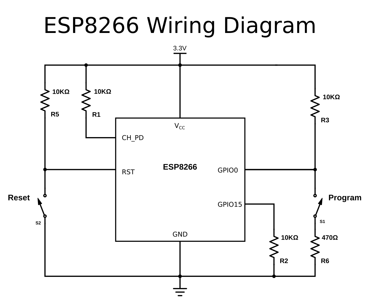
To upload a sketch:
1. press and hold the reset button
2. press and hold the program button
3. release the reset button, the ESP will boot in program mode
4. release the program button
5. upload the sketch
If your USB-to-Serial breaks out the RTS and/or DTR lines, you can automate the reset and programming mode procedures.
answered Sep 28 '17 at 13:40
tttapatttapa
945129
add a comment |
The ESP8266 has two "modes". "Run" mode and "Flash" mode. In "Run" mode the firmware installed onto the ESP8266 executes. The default firmware is the AT firmware that allows you to control the device with AT commands through serial.
Note that the site you link to has erroneous information about CH_PD that should be talking about GPIO0.
In "Flash" mode you get to upload new firmware (AKA a "sketch") to make the device do something different.
The basic programming sequence is:
- Switch the device to Flash mode (connect GPIO0 to GND)
- Upload the sketch using the IDE
- Switch the device to Run mode (connect GPIO0 to 3.3V).
Because of these extra steps many people choose to invest in a small USB interface board designed specifically for programming the ESP8266 to make their life easier. These generally have a switch on them to set whether GPIO0 is connected to GND or 3.3V.
answered Sep 28 '17 at 12:48
Majenko♦Majenko
68.1k43277
Thank you for the clarification. Really helps. I have connected the CH_PD to GND, I try to run the sketch but still pretty much get the same error:warning: espcomm_sync failed error: espcomm_open failed error: espcomm_upload_mem failed error: espcomm_upload_mem failedNot sure whats going wrong
– dfqupwndguerrillamailde
Sep 28 '17 at 13:04
Get an adaptor. It makes everything so much simpler. They're dirt cheap on eBay.
– Majenko♦
Sep 28 '17 at 13:19
Would this adapter work?: amazon.co.uk/gp/product/B06Y3FNGJF/…
– dfqupwndguerrillamailde
Sep 28 '17 at 13:20
This is incorrect. CH_PD turns the chip on or off. I think you mean GPIO0
– tttapa
Sep 28 '17 at 13:22
@tttapa I thought it was GPIO0 too, but the site linked to in the question says CH_PD.
– Majenko♦
Sep 28 '17 at 13:25
|
show 4 more comments
in the nodeMCU.i got the same issue while uploadin.
issue was that the mode was not selected to 'program mode' even after doing the below steps.
- press and hold the reset button
- press and hold the program button
- release the reset button, the ESP will boot in program mode
- release the program button
- upload the sketch
To solve the issue,do this
- short the pin GPIO 0(D3) to ground using a jumper wire.
- press reset button
- upload the sketch
- remove the jumper wire .
Done!!!!
edited Sep 15 '18 at 8:01
Michel Keijzers
6,69441938
answered Sep 15 '18 at 7:00
alex joshyalex joshy
1
add a comment |
Your Answer
StackExchange.ifUsing("editor", function () {
return StackExchange.using("schematics", function () {
StackExchange.schematics.init();
});
}, "cicuitlab");
StackExchange.ready(function() {
var channelOptions = {
tags: "".split(" "),
id: "540"
};
initTagRenderer("".split(" "), "".split(" "), channelOptions);
StackExchange.using("externalEditor", function() {
// Have to fire editor after snippets, if snippets enabled
if (StackExchange.settings.snippets.snippetsEnabled) {
StackExchange.using("snippets", function() {
createEditor();
});
}
else {
createEditor();
}
});
function createEditor() {
StackExchange.prepareEditor({
heartbeatType: 'answer',
autoActivateHeartbeat: false,
convertImagesToLinks: false,
noModals: true,
showLowRepImageUploadWarning: true,
reputationToPostImages: null,
bindNavPrevention: true,
postfix: "",
imageUploader: {
brandingHtml: "Powered by u003ca class="icon-imgur-white" href="https://imgur.com/"u003eu003c/au003e",
contentPolicyHtml: "User contributions licensed under u003ca href="https://creativecommons.org/licenses/by-sa/3.0/"u003ecc by-sa 3.0 with attribution requiredu003c/au003e u003ca href="https://stackoverflow.com/legal/content-policy"u003e(content policy)u003c/au003e",
allowUrls: true
},
onDemand: true,
discardSelector: ".discard-answer"
,immediatelyShowMarkdownHelp:true
});
}
});
Sign up or log in
StackExchange.ready(function () {
StackExchange.helpers.onClickDraftSave('#login-link');
});
Sign up using Google
Sign up using Facebook
Sign up using Email and Password
Post as a guest
Required, but never shown
StackExchange.ready(
function () {
StackExchange.openid.initPostLogin('.new-post-login', 'https%3a%2f%2farduino.stackexchange.com%2fquestions%2f45133%2ferror-espcomm-upload-mem-failed-when-uploading-a-sketch%23new-answer', 'question_page');
}
);
Post as a guest
Required, but never shown
3 Answers
3
active
oldest
votes
3 Answers
3
active
oldest
votes
active
oldest
votes
active
oldest
votes
By default, the ESP8266 runs the program in flash memory.
To upload new firmware over UART, you have to change the boot mode by connecting GPIO0 to ground during reset.
GPIO15 should be low and GPIO2 should be high during boot in both cases. GPIO needs an external pull-down resistor, the internal pull-up resistor for GPIO2 is enabled during boot, so you don't need to add an external one.
To prevent from shorting GPIO0 if it's used as an output in your sketch, it's recommended to add a series resistor to limit the current.
To upload a sketch:
1. press and hold the reset button
2. press and hold the program button
3. release the reset button, the ESP will boot in program mode
4. release the program button
5. upload the sketch
If your USB-to-Serial breaks out the RTS and/or DTR lines, you can automate the reset and programming mode procedures.
answered Sep 28 '17 at 13:40
tttapatttapa
945129
add a comment |
By default, the ESP8266 runs the program in flash memory.
To upload new firmware over UART, you have to change the boot mode by connecting GPIO0 to ground during reset.
GPIO15 should be low and GPIO2 should be high during boot in both cases. GPIO needs an external pull-down resistor, the internal pull-up resistor for GPIO2 is enabled during boot, so you don't need to add an external one.
To prevent from shorting GPIO0 if it's used as an output in your sketch, it's recommended to add a series resistor to limit the current.
To upload a sketch:
1. press and hold the reset button
2. press and hold the program button
3. release the reset button, the ESP will boot in program mode
4. release the program button
5. upload the sketch
If your USB-to-Serial breaks out the RTS and/or DTR lines, you can automate the reset and programming mode procedures.
answered Sep 28 '17 at 13:40
tttapatttapa
945129
answered Sep 28 '17 at 13:40
tttapatttapa
945129
answered Sep 28 '17 at 13:40
tttapatttapa
945129
answered Sep 28 '17 at 13:40
tttapatttapa
945129
945129
add a comment |
add a comment |
The ESP8266 has two "modes". "Run" mode and "Flash" mode. In "Run" mode the firmware installed onto the ESP8266 executes. The default firmware is the AT firmware that allows you to control the device with AT commands through serial.
Note that the site you link to has erroneous information about CH_PD that should be talking about GPIO0.
In "Flash" mode you get to upload new firmware (AKA a "sketch") to make the device do something different.
The basic programming sequence is:
- Switch the device to Flash mode (connect GPIO0 to GND)
- Upload the sketch using the IDE
- Switch the device to Run mode (connect GPIO0 to 3.3V).
Because of these extra steps many people choose to invest in a small USB interface board designed specifically for programming the ESP8266 to make their life easier. These generally have a switch on them to set whether GPIO0 is connected to GND or 3.3V.
answered Sep 28 '17 at 12:48
Majenko♦Majenko
68.1k43277
Thank you for the clarification. Really helps. I have connected the CH_PD to GND, I try to run the sketch but still pretty much get the same error:warning: espcomm_sync failed error: espcomm_open failed error: espcomm_upload_mem failed error: espcomm_upload_mem failedNot sure whats going wrong
– dfqupwndguerrillamailde
Sep 28 '17 at 13:04
Get an adaptor. It makes everything so much simpler. They're dirt cheap on eBay.
– Majenko♦
Sep 28 '17 at 13:19
Would this adapter work?: amazon.co.uk/gp/product/B06Y3FNGJF/…
– dfqupwndguerrillamailde
Sep 28 '17 at 13:20
This is incorrect. CH_PD turns the chip on or off. I think you mean GPIO0
– tttapa
Sep 28 '17 at 13:22
@tttapa I thought it was GPIO0 too, but the site linked to in the question says CH_PD.
– Majenko♦
Sep 28 '17 at 13:25
|
show 4 more comments
The ESP8266 has two "modes". "Run" mode and "Flash" mode. In "Run" mode the firmware installed onto the ESP8266 executes. The default firmware is the AT firmware that allows you to control the device with AT commands through serial.
Note that the site you link to has erroneous information about CH_PD that should be talking about GPIO0.
In "Flash" mode you get to upload new firmware (AKA a "sketch") to make the device do something different.
The basic programming sequence is:
- Switch the device to Flash mode (connect GPIO0 to GND)
- Upload the sketch using the IDE
- Switch the device to Run mode (connect GPIO0 to 3.3V).
Because of these extra steps many people choose to invest in a small USB interface board designed specifically for programming the ESP8266 to make their life easier. These generally have a switch on them to set whether GPIO0 is connected to GND or 3.3V.
answered Sep 28 '17 at 12:48
Majenko♦Majenko
68.1k43277
edited Sep 28 '17 at 13:26
answered Sep 28 '17 at 12:48
Majenko♦Majenko
68.1k43277
answered Sep 28 '17 at 12:48
Majenko♦Majenko
68.1k43277
answered Sep 28 '17 at 12:48
Majenko♦Majenko
68.1k43277
68.1k43277
Thank you for the clarification. Really helps. I have connected the CH_PD to GND, I try to run the sketch but still pretty much get the same error:warning: espcomm_sync failed error: espcomm_open failed error: espcomm_upload_mem failed error: espcomm_upload_mem failedNot sure whats going wrong
– dfqupwndguerrillamailde
Sep 28 '17 at 13:04
Get an adaptor. It makes everything so much simpler. They're dirt cheap on eBay.
– Majenko♦
Sep 28 '17 at 13:19
Would this adapter work?: amazon.co.uk/gp/product/B06Y3FNGJF/…
– dfqupwndguerrillamailde
Sep 28 '17 at 13:20
This is incorrect. CH_PD turns the chip on or off. I think you mean GPIO0
– tttapa
Sep 28 '17 at 13:22
@tttapa I thought it was GPIO0 too, but the site linked to in the question says CH_PD.
– Majenko♦
Sep 28 '17 at 13:25
|
show 4 more comments
Thank you for the clarification. Really helps. I have connected the CH_PD to GND, I try to run the sketch but still pretty much get the same error:warning: espcomm_sync failed error: espcomm_open failed error: espcomm_upload_mem failed error: espcomm_upload_mem failedNot sure whats going wrong
– dfqupwndguerrillamailde
Sep 28 '17 at 13:04
Get an adaptor. It makes everything so much simpler. They're dirt cheap on eBay.
– Majenko♦
Sep 28 '17 at 13:19
Would this adapter work?: amazon.co.uk/gp/product/B06Y3FNGJF/…
– dfqupwndguerrillamailde
Sep 28 '17 at 13:20
This is incorrect. CH_PD turns the chip on or off. I think you mean GPIO0
– tttapa
Sep 28 '17 at 13:22
@tttapa I thought it was GPIO0 too, but the site linked to in the question says CH_PD.
– Majenko♦
Sep 28 '17 at 13:25
Thank you for the clarification. Really helps. I have connected the CH_PD to GND, I try to run the sketch but still pretty much get the same error:
warning: espcomm_sync failed error: espcomm_open failed error: espcomm_upload_mem failed error: espcomm_upload_mem failed Not sure whats going wrong– dfqupwndguerrillamailde
Sep 28 '17 at 13:04
Get an adaptor. It makes everything so much simpler. They're dirt cheap on eBay.
– Majenko♦
Sep 28 '17 at 13:19
Get an adaptor. It makes everything so much simpler. They're dirt cheap on eBay.
– Majenko♦
Sep 28 '17 at 13:19
Would this adapter work?: amazon.co.uk/gp/product/B06Y3FNGJF/…
– dfqupwndguerrillamailde
Sep 28 '17 at 13:20
Would this adapter work?: amazon.co.uk/gp/product/B06Y3FNGJF/…
– dfqupwndguerrillamailde
Sep 28 '17 at 13:20
This is incorrect. CH_PD turns the chip on or off. I think you mean GPIO0
– tttapa
Sep 28 '17 at 13:22
This is incorrect. CH_PD turns the chip on or off. I think you mean GPIO0
– tttapa
Sep 28 '17 at 13:22
@tttapa I thought it was GPIO0 too, but the site linked to in the question says CH_PD.
– Majenko♦
Sep 28 '17 at 13:25
@tttapa I thought it was GPIO0 too, but the site linked to in the question says CH_PD.
– Majenko♦
Sep 28 '17 at 13:25
|
show 4 more comments
in the nodeMCU.i got the same issue while uploadin.
issue was that the mode was not selected to 'program mode' even after doing the below steps.
- press and hold the reset button
- press and hold the program button
- release the reset button, the ESP will boot in program mode
- release the program button
- upload the sketch
To solve the issue,do this
- short the pin GPIO 0(D3) to ground using a jumper wire.
- press reset button
- upload the sketch
- remove the jumper wire .
Done!!!!
edited Sep 15 '18 at 8:01
Michel Keijzers
6,69441938
answered Sep 15 '18 at 7:00
alex joshyalex joshy
1
add a comment |
in the nodeMCU.i got the same issue while uploadin.
issue was that the mode was not selected to 'program mode' even after doing the below steps.
- press and hold the reset button
- press and hold the program button
- release the reset button, the ESP will boot in program mode
- release the program button
- upload the sketch
To solve the issue,do this
- short the pin GPIO 0(D3) to ground using a jumper wire.
- press reset button
- upload the sketch
- remove the jumper wire .
Done!!!!
edited Sep 15 '18 at 8:01
Michel Keijzers
6,69441938
answered Sep 15 '18 at 7:00
alex joshyalex joshy
1
edited Sep 15 '18 at 8:01
Michel Keijzers
6,69441938
edited Sep 15 '18 at 8:01
Michel Keijzers
6,69441938
edited Sep 15 '18 at 8:01
Michel Keijzers
6,69441938
6,69441938
answered Sep 15 '18 at 7:00
alex joshyalex joshy
1
answered Sep 15 '18 at 7:00
alex joshyalex joshy
1
answered Sep 15 '18 at 7:00
alex joshyalex joshy
1
1
add a comment |
add a comment |
Thanks for contributing an answer to Arduino Stack Exchange!
- Please be sure to answer the question. Provide details and share your research!
But avoid …
- Asking for help, clarification, or responding to other answers.
- Making statements based on opinion; back them up with references or personal experience.
To learn more, see our tips on writing great answers.
Sign up or log in
StackExchange.ready(function () {
StackExchange.helpers.onClickDraftSave('#login-link');
});
Sign up using Google
Sign up using Facebook
Sign up using Email and Password
Post as a guest
Required, but never shown
StackExchange.ready(
function () {
StackExchange.openid.initPostLogin('.new-post-login', 'https%3a%2f%2farduino.stackexchange.com%2fquestions%2f45133%2ferror-espcomm-upload-mem-failed-when-uploading-a-sketch%23new-answer', 'question_page');
}
);
Post as a guest
Required, but never shown
Sign up or log in
StackExchange.ready(function () {
StackExchange.helpers.onClickDraftSave('#login-link');
});
Sign up using Google
Sign up using Facebook
Sign up using Email and Password
Post as a guest
Required, but never shown
Sign up or log in
StackExchange.ready(function () {
StackExchange.helpers.onClickDraftSave('#login-link');
});
Sign up using Google
Sign up using Facebook
Sign up using Email and Password
Post as a guest
Required, but never shown
Sign up or log in
StackExchange.ready(function () {
StackExchange.helpers.onClickDraftSave('#login-link');
});
Sign up using Google
Sign up using Facebook
Sign up using Email and Password
Sign up using Google
Sign up using Facebook
Sign up using Email and Password
Post as a guest
Required, but never shown
Required, but never shown
Required, but never shown
Required, but never shown
Required, but never shown
Required, but never shown
Required, but never shown
Required, but never shown
Required, but never shown


1
Did you take note of the paragraph in your first link that reads
And since we talked about the CH_PD pin, remember that if you want to flash the ESP8266 you should connect the GPIO0 pin to GND (blue line), which puts the ESP into flash mode.– Majenko♦
Sep 28 '17 at 12:32
@Majenko I am able to send AT commands with the module so should I not be in flash mode when trying to send a http request? Also, does flashing mean upgrading the firmware in the esp2866?
– dfqupwndguerrillamailde
Sep 28 '17 at 12:44